This was my first shot to create a walker robot from scratch. Wheels were just too easy 🙂 . The parts were designed with Alibre and milled on my Tormach CNC machine. I designed my own servo controller board using an ATMega168. The PWM signals were created in software because the design goal was to control up to 18 servos and the ATMega only supported up to two HW PWM. PWM requires precise timing, this pretty much used up all resources, I couldn’t use this MCU for anything other than a SPI client which reads the PWM positions. Later, I added an AVR32 which sends the position signals to the ATMega168 and in addition also reads the sensor data from the FSR sensors attached to the legs and accelerometer. I milled the first PWM controller PCB, just to see how things worked.


This video is showing the initial testing at the Vancouver Robotics Club. The PCB milled control board doesn’t have the ARV32 chip yet. FSR sensors were later added to the legs.
Control board on a bread board


The final Control board layout was designed with Eagle. I uploaded the Gerber files to a fab house and 3 weeks later I received the PCBs.


Control board – with mounting bracket milled from acrylic


Control board testing
FSR sensor test (Force Sensing Resistor)
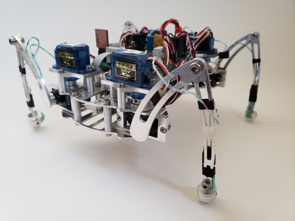
The finished walker


")
")
")
")

")